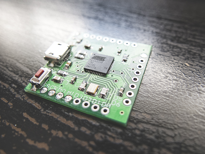
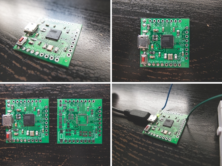
 I’m currently working on a project that requires a stand-alone microcontroller as the “brain” of the system. A few weeks ago I designed the PCB and sent it to get manufactured. It finally arrived and I was able to test it. So far everything functions well.
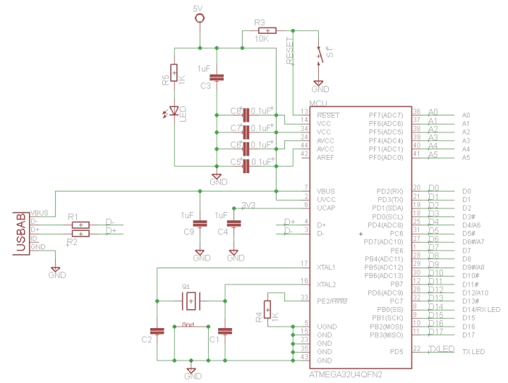
It uses the same IC as the Arduino Leonardo, ATmega32u4, but in a smaller package (QFN), and the PCB is only 30mm x 30mm! I decided to use this microcontroller since I can easy upload the bootloader (see below) and program it as I would an Arduino (through the Arduino IDE or Atmel Studio). The basic setup is as such:
The IC I have doesn’t have the Arduino bootloader on it so I needed to burn it. But before doing that I connected the PCB to the USB port of my computer to see if it will be recognized, and it was! The device manager shows it as ATmega32u4. That gave me the confidence to go ahead and burn the bootloader USING my Arduino. To burn a bootloader to an Atmel chip such as the ATmega, we connect PINS 10, 11, 12 and 13 on the Arduino to RESET, MOSI, MISO, and CLOCK pins on the ATmega. 10 -> RESET 11 -> MOSI 12 -> MISO 13 -> SCLK If you look at the ATmega32u4 datasheet ( http://www.atmel.com/Images/Atmel-7766-8-bit-AVR-ATmega16U4-32U4_Summary.pdf ) we find that the SCLK, MOSI and MISO pins correspond to pins PB1 , PB2 and PB3 respectively. Before connecting the Arduino to the PCB, upload the ArduinoISP sketch to the Arduino. File -> Examples -> ArduinoISP. Then (with the Arduino unplugged): 1. Connect a 1uF capacitor between the RESET pin and GND on the Arduino to disable the auto-reset function. 2. Now, connected the Arduino to the PCB as above, and go to the Arduino IDE. 3. Select Arduino Leonardo as your board (this corresponds to the ATmega32u4 chip on the PCB). 4. Tools -> Programmer -> Arduino as ISP 5. Tools -> Burn Bootloader And you’re done! It might take about 30 seconds. The bootloader loads the Blink sketch to your chip so you should see PIN13 switching ON and OFF every second. Your PCB is ready to be programmed via the USB port. Disconnect all wires and try it for yourself. Good luck! 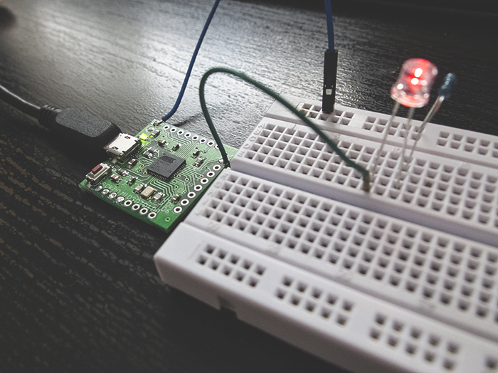
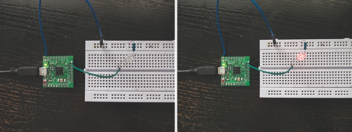 This is the first version of the PCB and I’m already seeing places for improvement. In a future version I might add an LED to PIN 13 so that I can test the bootloader without external connections. Also, it will be beneficial if there were designated ICSP programming pins. The board is only 30mmx30mm and already populated to max. capacity so it might be hard to do.

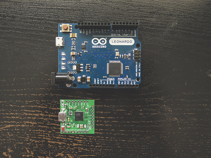
You hava a part number of this crystal and this usb conector?