As promised, here’s the rest of the code for the battery management system. The BMS now reads the voltage of each battery cell and balances each cell until the battery voltage across all cells is closely matched; +/-0.03V.
I also included a box with a switch and an LCD display. Some extra components are included such as a small trimmer potentiometer to adjust the LCD brightness, DIP switch with 4 contacts, toggle switch to turn power-off and on and a box to store the components.
This is what the new setup looks like:


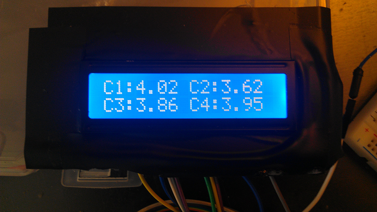
And here’s the result:
1.This is the starting position of the 4 lithium batteries.
2. Then the batteries begin to discharge.

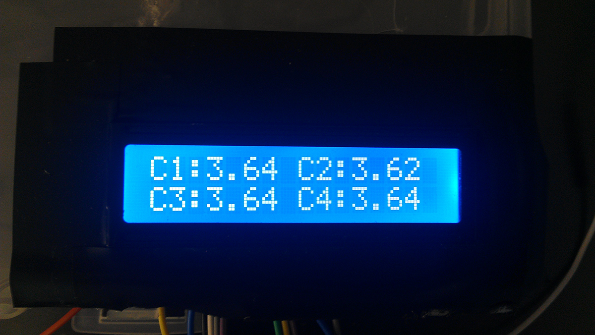
3. And at the end, the battery voltages are closely matched.
Here’s the new code:
#include "SPI.h"
#include <LiquidCrystal.h>
// SDO - PIN 12
// SDI - PIN 11
#define WRCFG  0x01 //Write Configuration Registers
#define RDCFG  0x02  // Read config
#define RDCV   0x04  // Read cells

#define STCVAD 0x10  // Start all A/D's - poll status
#define RDFLG  0x06 //Read Flags
#define RDTMP  0x08 //Read Temperatures

#define STCDC  0x60 //A/D converter and poll Status
#define STOWAD 0x20 //Start Test - poll status
#define STTMPAD 0x30// Temperature Reading - ALL

#define address 0x80
//Functions
#define TOTAL  4
#define LIMIT 0.01
byte byteTemp;
byte CFGR1 = 0x00;
byte CFGR2 = 0x00;
float cellVolt[TOTAL];

LiquidCrystal lcd(7,6,5,4,3,2);


void setup()
{
pinMode(10,OUTPUT);
pinMode(11,OUTPUT);
pinMode(12,INPUT);
pinMode(13,OUTPUT);
digitalWrite(10, HIGH);
SPI.setBitOrder(MSBFIRST);
SPI.setDataMode(SPI_MODE3);
SPI.setClockDivider(SPI_CLOCK_DIV16);
SPI.begin();
Serial.begin(9600);
//LCD Setup
lcd.begin(16,2);
lcd.setCursor(0,0);
lcd.print("C1: ");
lcd.setCursor(8,0);
lcd.print("C2: ");
lcd.setCursor(0,1);
lcd.print("C3: ");
lcd.setCursor(8,1);
lcd.print("C4: ");
//lcd.print("Hello world!");
writeReg(); //Initial setup
}

void loop()
{
readV();
//Serial.print("Lowest cell: "); Serial.print(lowCell()); Serial.print(" , Value: "); Serial.println(cellVolt[lowCell()-1]);
//Serial.print("Highest cell: "); Serial.print(highCell()); Serial.print(" , Value: "); Serial.println(cellVolt[highCell()-1]);
startBalance();
//delay(2000);
Serial.println(CFGR1,BIN);
lcd.setCursor(3,0);
lcd.print(cellVolt[0]);
lcd.setCursor(11,0);
lcd.print(cellVolt[1]);
lcd.setCursor(3,1);
lcd.print(cellVolt[2]);
lcd.setCursor(11,1);
lcd.print(cellVolt[3]);
delay(1000);
}

void writeReg()
{
 Serial.println("Writing config...");
  digitalWrite(10, LOW);
  SPI.transfer(address);
  SPI.transfer(WRCFG);
  SPI.transfer(0x01);//0
  SPI.transfer(CFGR1);//1
  SPI.transfer(CFGR2);//2
  SPI.transfer(0x00);//3
  SPI.transfer(0x71);//4
  SPI.transfer(0xAB);//5
  digitalWrite(10, HIGH);
}
void readReg()
{
Serial.println("Reading config...");
digitalWrite(10, LOW);
   SPI.transfer(address);
   SPI.transfer(RDCFG);
   for(int i = 0; i < 6; i++)
   {
   byteTemp = SPI.transfer(RDCFG);
   Serial.println(byteTemp, HEX);
   }
  digitalWrite(10, HIGH);
}
void readV()
{
  digitalWrite(10,LOW);
  SPI.transfer(STCVAD);
  delay(20); // wait at least 12ms as per data sheet, p.24
  digitalWrite(10,HIGH);
  byte volt[18];
  digitalWrite(10,LOW);
  SPI.transfer(0x80);
  SPI.transfer(RDCV);
  for(int j = 0; j<18;j++)
  {
  volt[j] = SPI.transfer(RDCV);
  }
  digitalWrite(10,HIGH);
  cellVolt[0] = (((volt[0] & 0xFF) | (volt[1] & 0x0F) << 8)*1.5*0.001);
  cellVolt[1] = (((volt[1] & 0xF0) >> 4 | (volt[2] & 0xFF) << 4)*1.5*0.001);
  cellVolt[2] = (((volt[3] & 0xFF) | (volt[4] & 0x0F) << 8)*1.5*0.001);
  cellVolt[3] = (((volt[4] & 0xF0) >> 4 | (volt[5] & 0xFF) << 4)*1.5*0.001);
  Serial.println(cellVolt[0]);
  Serial.println(cellVolt[1]);
  Serial.println(cellVolt[2]);
  Serial.println(cellVolt[3]);
  Serial.println("--------------------");
}

int startBalance()
{
 CFGR1 = 0x00;
 CFGR2 = 0x00;
 int low = lowCell();
 for(int i = 1; i < TOTAL+1; i++)
 {
 if(i != low)
 {
 balanceCell(i);//set each cell individually; discharge if not lowest cell
 }
 }
 Serial.println(CFGR1,BIN);
 Serial.println(CFGR2,BIN);
 writeReg();

}

int balanceCell(int x)
{
  double diff = cellVolt[x-1] - cellVolt[lowCell()-1]; //check the difference between current cell and lowestCell
  if(x <= 8 && diff > 0.03)	//discharge if difference more than 0.03V
  {
  CFGR1 += 0x01<<(x-1);
  }
  if(x <= 8 && diff <= 0.03)
  {
  CFGR1 += 0x00<<(x-1);
  }
  if(x > 8 && diff > 0.03)
  {
  CFGR2 += 0x01<<(x-9);
  }
  if(x > 8 && diff <= 0.03)
  {
  CFGR2 += 0x00<<(x-9);
  }

}

int highCell() //find highest voltage cell value
{
  int num = 0;
  float cellTemp = 0;
  for(int i = 0; i < TOTAL;)
  {
    if(cellVolt[i] > cellTemp)
    {
      cellTemp = cellVolt[i];
      num = i+1;
    }
    i++;
  }
  return num;
}

int lowCell() //find lowest cell value
{
  int num = 0;
  float cellTemp = 5;
  for(int i = 0; i < TOTAL;)
  {
    if(cellVolt[i] < cellTemp)
    {
      cellTemp = cellVolt[i];
      num = i+1;
    }
    i++;
  }
  return num;
}
(If WordPress doesn’t display the code correctly here’s a link to the file)
https://www.sendspace.com/file/91rwxs
*A few additional safety features are needed before the BMS is complete. Such as: low voltage warning and action, high voltage warning, temperature sensing and a current sensor to monitor the charging current as well as the SOC (state-of-charge) of the battery pack.

Quote “closely matched; +/-0.3V”
Should this be 0.03? .3v seems a LOT compared to a 4v battery!
You are Correct! It should be +/- 0.03V
hello, can i ask if this is possible converting to active cell balancing?
If you look at the datasheet for this chip (LTC6802-2) they only mention passive balancing (using a resistor). You might be able to do it with some sort of an external circuit but I’m not sure at this point.
Hi, smallvill3 hope you’re still active here, just wanna ask if how you learn to code the chip? do you learn assembly language or C? and how to know how to send command to the chip?
From my code you can see that it’s done in C/C++. The chip is accessible via the SPI interface. All you have to do is pull-down the chip-select pin and send the appropriate command (look up arduino SPI). You can find the commands’ list on Table 9, page 20, in the datasheet for this chip. I also recommend learning more about microcontrollers and registers. In parts of my code I shift the bits inside the register to get the right data.
I’ve learned this by practicing with a few example projects and then doing it at my work. Once you learn about the basics of microcontrollers and the different interfaces (SPI, UART, I2C etc) it will get easier when coding new chips.
I hope this helps. Good luck.
Wow thanks a lot really appreciate your help! I am planning to use LTC3300-1 (for active balancing) and LTC6802 (for voltage monitoring). Do you think arduino UNO can handle this using SPI? or I need to get higher MCU? Btw, I need to measure and balance 12cells. Thanks, and God Bless always.
hello smallville! can i ask some questions? We are doing this same kind of project as yours, hope you can help us 🙂
Hello Smallville, Thanks for your 2 Articles on this. It has pointed me to the right IC for this need. Was doing the same based on Raspberry but hadn’t foud the 6802-2 yet. Your article gives me a real headstart now. Have you done the SOC via a shunt yet? Or haven’t you come around to upgrading it further.
Hi Henk,
I haven’t done anything else with this IC.
Hey Smallville, got a quick question, what values of resistors did you use to discharge the cells and how did you decided to go with those values ? Hopefully you’re still active on this blog.
Hi SMALLVILL3,
Hopefully you’re still active on this blog. Just wondering what value of resistor did you use to discharge the cells and how did you go about choosing those values.
Hi,
I’m using 33OHM resistors. I picked these because they provide a decent battery discharge but don’t allow too much current to flow through. ~(3.7 V/33 Ohm) = 11mA. You can probably lower the values to get a faster discharge. I found this was adequate enough for me.
I hope this helps.